3-Element Yagi: The 3-element Yagi antenna, described below, was removed from service 7 June 2010, almost 2 years after original installation. It was replaced by an 8-element log period dipole array antenna described here.
The 3-element Yagi includes an antenna support structure, antenna rotator, antenna, impedance matching components and transmission line. Because of the overriding need to preserve local foliage, mainly for aesthetic reasons, the antenna installation is surrounded by deciduous trees and conifers and is far from optimum. The antenna site elevation is approximately 13 m AMSL and is about 200 m from the shore of Cook Inlet.
Click here for a description of the antenna supporting structure (tower).
The Yagi antenna is directional with an advertised gain of 7.5 dBi and 3 dB beamwidth of 60 degrees. It is mounted on a rotatable shaft at the top of the tower approximately 13.8 m above ground level (AGL).
This antenna is used primarily for Radio JOVE experiments. It is tuned to about 21 MHz with a bandwidth of a several hundred kHz. The antenna uses a Beta Match and a current balun for connection of the antenna driven element to a 50 ohm coaxial cable transmission line. The coaxial cable is 10 mm diameter Times Microwave LMR-400-DB (direct burial) and is approximately 50 m long.
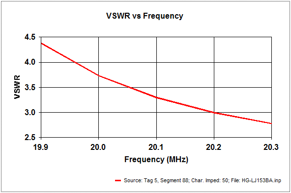
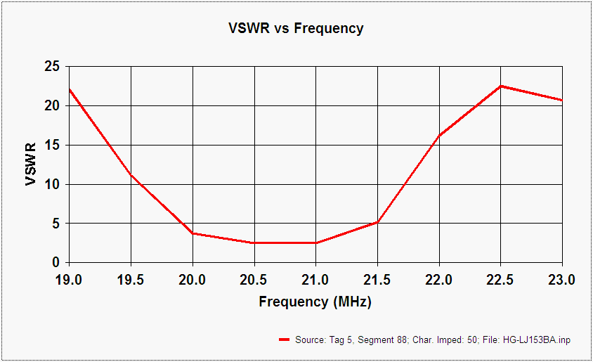
Although the antenna originally was designed for the 15 m amateur radio band (21.00 to 21.45 MHz), we investigated it in the range of 19 to 23 MHz. We found the useful range is approximately 20.0 to a little over 21.5 MHz.
Antenna elevation and azimuth patterns, impedance and SWR for various frequency ranges are here:
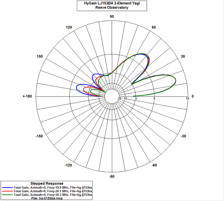
- Azimuth of main lobe in 0.2 MHz steps from 19 to 23 MHz
- Azimuth of secondary lobe in 0.2 MHz steps from 19 to 23 MHz
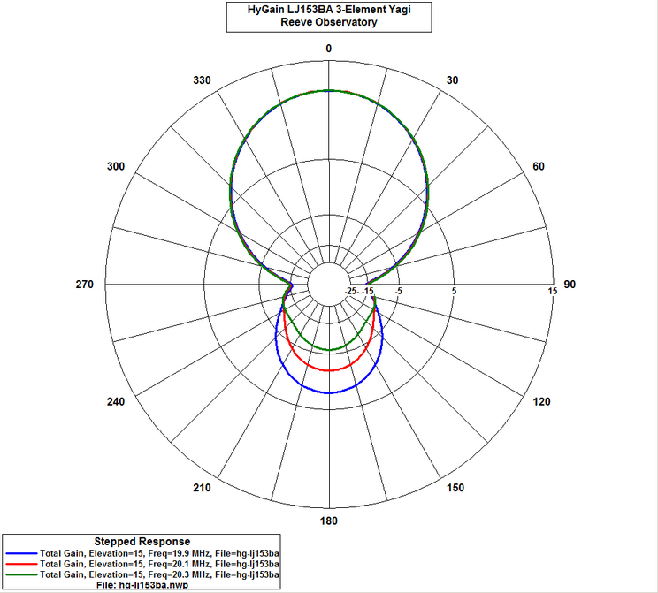
- Elevation in 0.2 MHz steps from 19 to 23 MHz
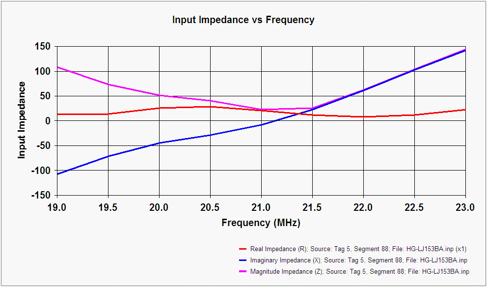
- Impedance from 19 to 23 MHz
- SWR from 19 to 23 MHz
Animations showing how the azimuth and elevation patterns change with frequency are here:
- Azimuth pattern of main lobe in 0.2 MHz steps from 19 to 23 MHz
- Elevation in 0.2 MHz steps from 19 to 23 MHz
The rotator is a Yaesu G-450A, which is mounted on the tower at approximately 12.5 m AGL with a plate-mounted bearing located above it to provide lateral support. The rotator is controlled by an MDS RC1-G Digital Rotor Control through 50 m of 6-conductor outdoor control cable. The RC1-G serial port is connected to the laboratory Ethernet LAN through a B&B Electronics ESP901 EIA-232-to-Ethernet converter. This converter's virtual COM port mode allows the rotator to be controlled from a station PC using Ham Radio Deluxe software or the Telepost LP-Rotor software.
Click here for a rotor control diagram.
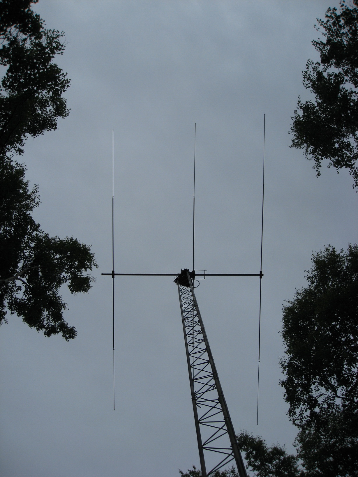
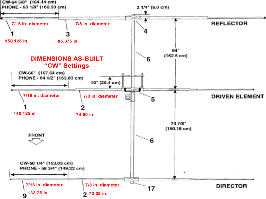
The antenna shown here is a Hy-Gain LJ-153BA, 3-element
Yagi.
A Yaesu G-450A rotator is used to point the antenna. The antenna is
primarily used in the frequency range of 20 - 21 MHz (15 m).
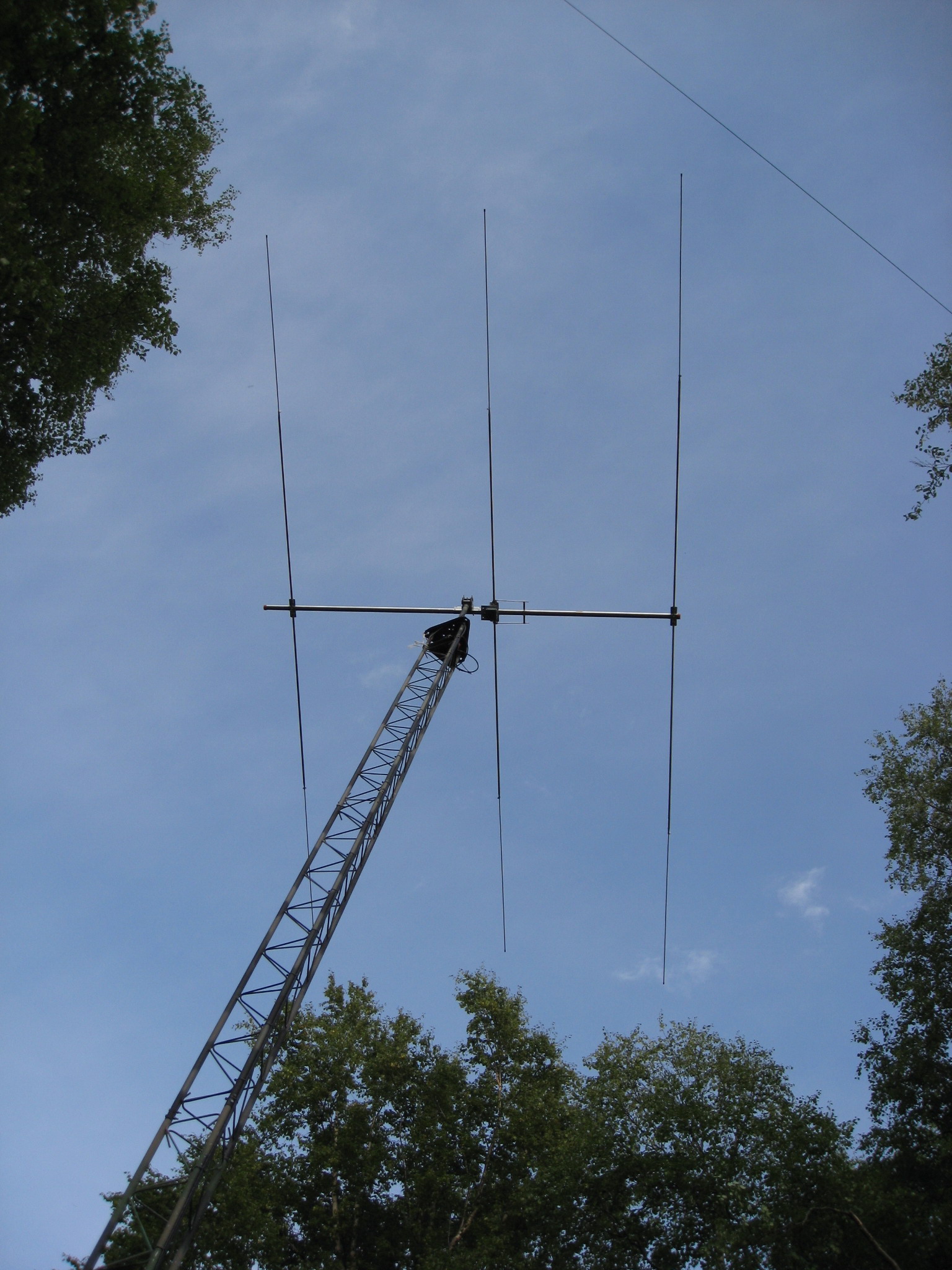
Another photograph of the LJ-153BA Yagi antenna (the stripes
seen on the
antenna elements are artifacts of the digital photograph). The element
lengths are: Reflector - 7.60 m (spacing from driver - 1.626 m); Driver -
7.06 m;
Director - 6.77 m (spacing from Driver - 1.902 m). The total boom
length is
3.66 m. An unrelated Beverage antenna can be seen crossing the view at
the upper-right.
The LJ-153BA was put together on the ground, as shown
below, and then
raised using the gin pole.
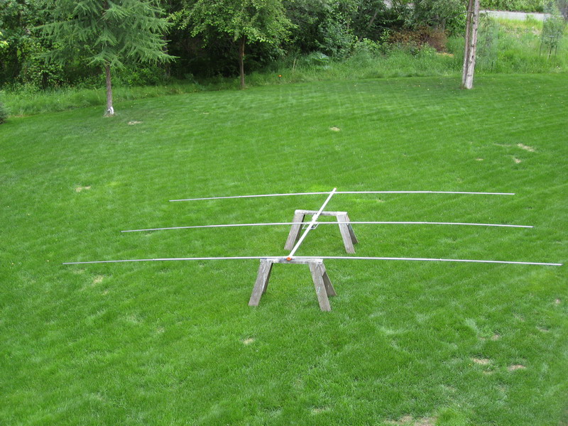
The LJ-153BA originally was designed for the 15 m
band (21.00 - 21.45 MHz).
The as-built dimensions of the antenna are shown below.
We investigated the antenna patterns and standing
wave ration (SWR) for slightly lower
frequencies between 19.9 and 20.3 MHz using NEC-WIN+ antenna modeling software
in "Step" mode. The maximum gain is about 12.6 dBi at 15 deg. elevation
angle.
The pattern and SWR plots are shown below.