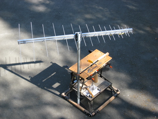
17-Element Very High Frequency/Ultra High Frequency Log Period Dipole Array: The 17-element VHF/UHF LPA antenna was placed in service on 26 May 2010 (see pictures below) and removed from service 1 June 2011. It was replaced by the Creative Design CLP5130-1N described here.
The 17-element LPA is model KMA144-500 by KMA Antennas (www.kmaantennas.com/). The characteristic impedance of the antenna is about 50 ohms. A choke balun made from ferrite beads reduces common-mode currents on the transmission line.
The LPA antenna installation includes an antenna support structure, antenna rotator, and transmission line. The antenna site elevation is approximately 13 m AMSL and is about 200 m from the shore of Cook Inlet. The antenna uses a pipe mount as shown in the pictures.
The LPA is a directional antenna with an a gain of approximately 7 to 10 dBi and 3 dB beamwidth of approximately 60 degrees, both determined from antenna models provided by the manufacturer. It is mounted on a rotatable shaft at the top of the pipe mast approximately 13.5 m above ground level (AGL). The coaxial cable transmission line is 10 mm diameter Terrawave TWS-400 and is approximately 15.5 m long.
The boom length is 6 ft and consists of two square aluminum tubes, which form a transmission line. The elements are alternated, effectively transposing the transmission line. The longest element is approximately 1/2-wavelength at 144 MHz (3.6 ft) and the shortest element is approximately 1/2-wavelength at 500 MHz. The turning radius is 4 ft.
The antenna system uses a Yaesu G-450A rotator. The rotator is controlled by an MDS RC1-G Digital Rotor Control through ~50 m of 6-conductor outdoor control cable. The RC1-G serial port is connected to the laboratory Ethernet LAN through a B&B Electronics ESP901 EIA-232-to-Ethernet converter. This converter's virtual COM port mode allows the rotator to be controlled from a station PC using Ham Radio Deluxe software or YO3DMU PstRotatorAz software. Click here for a rotor control diagram.
Results from antenna modeling will be posted later.
Antenna on test stand. The antenna was connected to a vector network analyzer to quickly determine its characteristics.

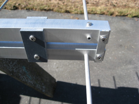
Front of antenna showing choke balun connection to double boom
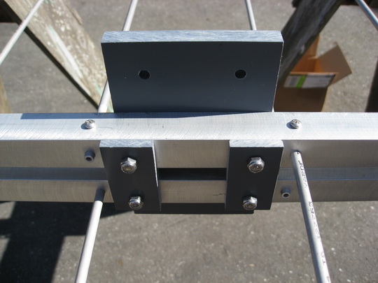
Rear of antenna showing short circuit termination
Plastic boom spacers (foreground) and plastic
mounting plate for antenna support (back). Boom spacers also are equipped at the
front
and rear of antenna.
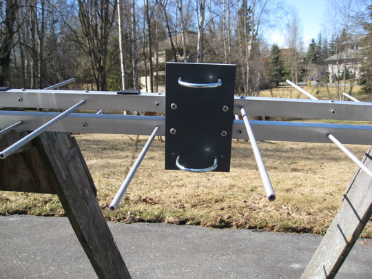
Plastic mounting plate for antenna pipe mount support
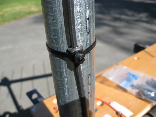
Coaxial cable support detail. Rubber mastic was
cut in strips, wrapped around the coax and secured to support with cable
ties. The rubber mastic prevents the crushing of the coaxial cable.
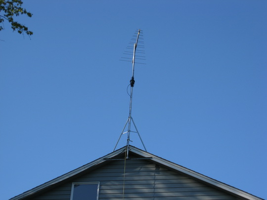
Antenna ready of service, 26 May 2010, showing
pipe mount and rotator. The pipe mount is braced at four points using a Rohn
Gable End Mount (GEM) and TRT60 tripod. The tripod was modified by removing one
leg.
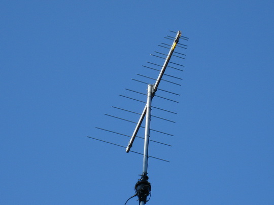
Antenna and rotator
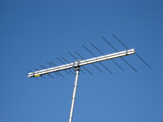
Antenna against blue sky pointed north