CALLISTO Antenna Installation
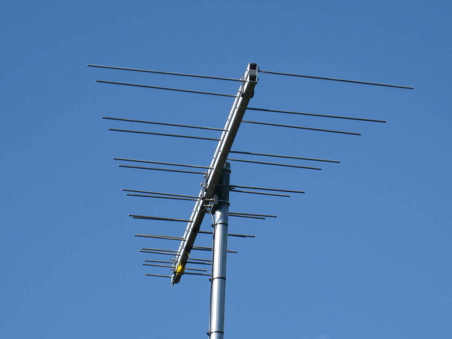
The permanent antenna system installation was placed in service on 3 June 2011. It consists of a Creative Design CLP5130-1N log periodic antenna, low noise amplifier (or preamplifier) and Yaesu G-800SA rotator.
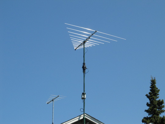
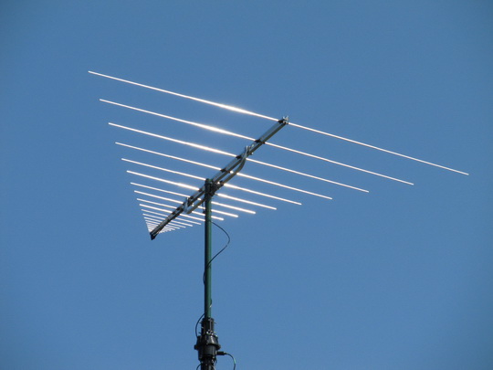
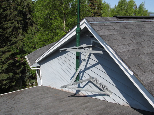
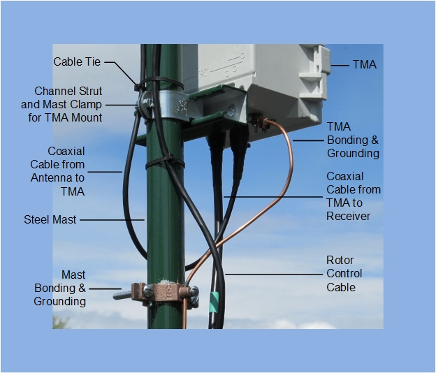
Present Antenna System: The antenna consists of a Creative Design CLP5130-1N with 21 elements and advertised gain of 10 ~ 12 dBi and bandwidth of 50 ~ 1300 MHz. The mast-mounted rotator and low-noise amplifier assembly are seen immediately below the antenna. Additional photographs show close-ups of the amplifier and mast mounting structure (Rohn Pole Wall Mount, model PWM). A description of the low-noise preamplifier and rotator controller is given below. The rotator is controlled by a modified controller and is controlled by PstRotator software, which is run in the Sun-tracking mode. A KMA144-500 antenna (since replaced with a CLP5130-1N) is seen in the background.
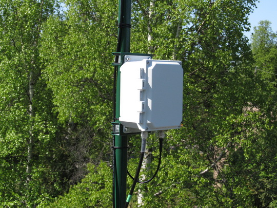
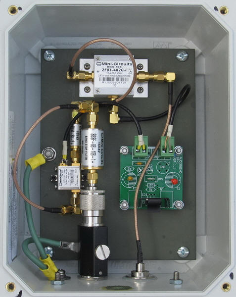
Low-Noise Amplifier Assembly: Major components in the tower-mounted LNA are lightning arrestor, Mini-Circuits ZX60-33LN+ LNA, Mini-Circuits VLM-33+ limiter, Mini-Circuits ZFBT-4R2G-FT+ Bias-Tee, 3.3 Vdc voltage regulator, grounding/bonding components and input/output RF connectors. The assembly shown here includes a Mini-Circuits SBSF-88-108 bandstop FM broadcast filter. All components are mounted on a primer painted aluminum plate that can be easily removed and replaced in less than 5 minutes.
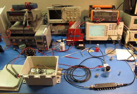
Low-Noise Amplifier Assembly Under Test: Low-noise amplifier assembly (lower-left) and input/output attenuators and spectrum analyzer with tracking generator used for testing.
Low Noise Amplifier Power Coupler Assembly (LPC): The LPC is fed by 12 Vdc station power supply and includes a Mini-Circuits ZFBT-4R2G-FT+ Bias-Tee (top) and 8.0 Vdc voltage regulator (right) to feed the remote tower-mounted low-noise amplifier assembly. Input/output RF connectors (bottom-left and -right) and all other components are mounted in an aluminum enclosure.

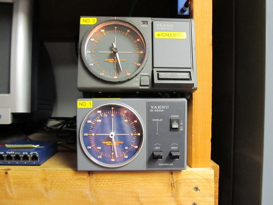
Rotator Controller: Modified controllers for Yaesu G-800SA (top) and G-450A (bottom). The G-800SA is used with e-CALLISTO and the G-450A is used with an HF log periodic antenna. Modifications include installation of an Easy Rotor Control circuit board from Engineering Office de Alba E. Schmidt and a 12 Vdc power supply inside each controller enclosure to allow remote control through the observatory LAN.
Interim Antenna System:
The CALLISTO Receiver and associated antenna originally were placed in interim service on 12 February 2011. The receiver was then relocated and the antenna system revised on 3 June 2011. The interim antenna system shown below used a KMA Antennas KMA144-500 log periodic antenna located on the north roof of the observatory. The antenna, which has an advertised bandwidth of 144 ~ 500 MHz, used a Yaesu G-450A rotator and modified controller for remote operation over the local area network. The motor running capacitor in the rotator body and one of the motor windings failed after a few months, and a new antenna system was installed at the south end of the roof.