Simple Aurora Monitor (SAM) Description and Specifications
![]()
The Simple Aurora Monitor (SAM) magnetometer system is a sophisticated semi-professional geomagnetometer designed by Dirk Langenbach (hardware) and Karsten Hansky (software).
The primary application of the SAM is in the sensing and study of geomagnetism, but it is possible to use the SAM in other applications requiring magnetic sensing. The correspondences between geomagnetic storms, solar events and solar wind, aurora and radio propagation anomalies are well-known. The SAM will be a useful instrument to radio astronomers, radio amateurs, aurora photographers and experimenters.
Click here for an article that includes a tutorial on geomagnetism as well as a description of the Simple Aurora Monitor used in our observatory.
 The SAM forms the basis for a
magnetometer network in Europe. We wish to expand this to a worldwide
amateur geomagnetometer network. It is our goal to deploy the SAM on every
continent. The southern hemisphere is under-represented even in
professional geomagnetometer chains and networks, so we are particularly
interested in deploying the SAM in southern latitudes. To become a member
of the SAM network, internet access is required.
The SAM forms the basis for a
magnetometer network in Europe. We wish to expand this to a worldwide
amateur geomagnetometer network. It is our goal to deploy the SAM on every
continent. The southern hemisphere is under-represented even in
professional geomagnetometer chains and networks, so we are particularly
interested in deploying the SAM in southern latitudes. To become a member
of the SAM network, internet access is required.
Click here for SAM ordering information
The basis for the SAM is a fluxgate magnetometer sensor manufactured by Speake & Company, Ltd. The sensor signals are processed by a Microchip PIC16F877 microcontroller operating at 16 MHz and associated logic circuitry.
Sensor outputs, K-index and time and date are shown on a liquid crystal display. Additional interface circuitry provides serial data, analog signal outputs and alarm outputs for external processing and display on a PC or voltmeter. The processor can be set to provide a dry contact alarm relay closure when the K-index exceeds a predetermined value. The alarm function is useful to aurora photographers and radio amateurs because it could indicate aurora picture and radio propagation opportunities.
The SAM may be operated in an autonomous (standalone) mode or it may be used with a PC for logging and viewing.
The basic specifications for the SAM magnetometer system are
-
Magnetic induction range: Approximately ± 20000 nT
-
Resolution: 1 – 2 nT
-
Connection of 2 sensors (to be expanded to 3 sensors in future version)
-
Microprocessor controlled, 16 MHz clock
-
Data displayed on backlit 4x20 LCD
-
Data transmitted over EIA-232 serial interface as ASCII text
-
Measurements available on two analog outputs (adjustable 0 ... +5 v or -2.5 ... +2.5 v)
-
Real-time clock
-
Isolated Form A relay output for K-index alarm
-
Isolated input for detection of external voltage condition
-
Software setup and measurement logging via EIA-232 serial-interface
-
Power requirements: 12 vdc at 60-70 ma
-
Temperature sensing capability (not yet supported in North American version)
-
Software setup and data logging and viewing
The setup software used with the SAM allows the user to adjust the SAM onboard parameters for standalone operation. When the SAM is connected to a PC running the included logging and viewing software, the software collects data from the SAM and provides additional downstream processing and archiving of magnetometer data. The software also produces a graphics file that may be viewed locally by any graphics viewing program or transmitted by File Transfer Protocol (FTP) to a web server for viewing on the internet.
Logging and viewing software screenshot.
The dark blue line is previous day data
and the
red line is current day data. This particular graph shows a
geomagnetic
storm that occurred
on July 22, 2009 (red line) starting at approximately 0300 UTC
and resulted in very good
aurora farther south than normal.
Click on the image to go to real time
data from our
Anchorage observatory.

Because of the magnetometer sensor sensitivity, it normally is installed at a remote location away from man-made magnetic disturbances; we are aware of sensor installations greater than 60 m from the SAM processor. We can provide information for locating the sensor at greater distances.
Click here to download the SAM construction manual and software setup manual.
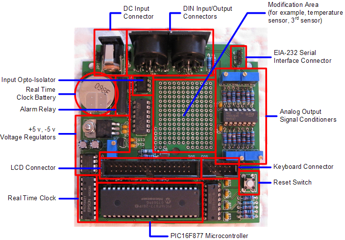
The SAM consists of a main controller printed circuit board (PCB), keyboard PCB and Liquid Crystal Display (LCD) module. The controller PCB is shown below.
Although the SAM includes viewing and logging software specifically designed for it, it can be used with other logging methods. When in standalone mode (not connected to a PC), SAM only displays the real time data and does not remember it. If a user needs to log data but does not wish to have SAM connected to a PC, the analog outputs can be connected to a datalogger.
The analog outputs can be adjusted for a range of 0 to +5 v or -2.5 to +2.5 v, so any datalogger compatible with these ranges should work with SAM. The datalogger software or common spreadsheet programs then can be used to chart, analyze and display the data. Data loggers are available that store the data on a SD memory card (for example, MPL-1000 and Elektor Datalogger deLuxe)
Some users have written custom application programs that use the EIA-232 serial port to collect data for analysis and display.
Click here for real time display of the SAM running in our Anchorage observatory