Raspberry Pi Network Time Server ~ GpsNtp-Pi
GpsNtp-Pi is a network time server that uses the Network Time Protocol, a GNSS receiver and the Raspberry Pi (RPi) computer platform. It will operate in standalone mode without any other time servers or in pooled mode with other time servers. GpsNtp-Pi can operate with an offset < ± 5 microseconds, about 4 orders of magnitude better than most PCs.
Applications
Using the Network Time Protocol (NTP), GpsNtp-Pi serves Coordinated Universal Time (UTC) to computers and PCs running an NTP client program. The NTP clients may access the time server on a LAN or WAN.

Ordering
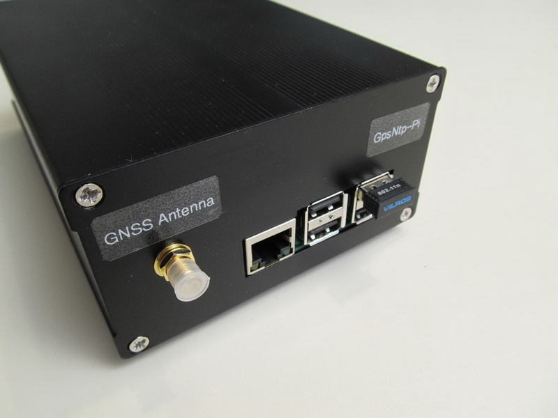
The GpsNtp-Pi is available as a special order - please inquire. It includes the RPi platform with GNSS receiver, extruded aluminum enclosure, dc-dc converter and associated filters, GNSS antenna with 3 m coaxial cable, assembled and tested. Operation is from 8 to 16 Vdc.
![]()
Operation
GpsNtp-Pi receives time and position information from GPS and GLONASS satellites and produces accurate time for distribution on a network. In standalone mode, GpsNtp-Pi relies only on the Global Navigation Satellite System (GNSS) satellites to provide accurate time. It uses both the NMEA protocol and pulse-per-second (PPS) to acquire and maintain the time. In pooled mode, GpsNtp-Pi can use other NTP servers on the LAN or WAN to increases system reliability and performance.
Specifications
- Platform: Raspberry Pi Model B+ or model 2 (also works with Model B)
- GNSS receiver: Global Technology FGPMMOPA6H or uBlox MAX-M8Q
-
Power requirements (nominal):
Packaged system (shown below): 12 Vdc, 5 W (2.1x5.5 mm coaxial power jack)Electronic assembly only, including Raspberry Pi platform and GNSS receiver: 5 Vdc, 2.5 W
-
Software: 8 GB or 16 GB micro-SD memory card in SD carrier
- 10/100BaseT Ethernet or 802.11b/g/n Wi-Fi
- No keyboard, mouse or monitor required
Documentation
Block diagram

Production system


Prototype Images ~ System 1 with GTop GNSS Receiver and External Antenna
The prototype system pictured below is based on the Adafruit "Ultimate GPS Hat" assembly and a Raspberry Pi model B+. An XP Power model SR10S05, 5 W dc-dc converter is used along with a pi-input filter to convert an input voltage range of 7 ... 18 Vdc to +5Vdc for the RPi. The power supply board also includes a polarity guard diode and additional MLC filter capacitors.