Loop Antenna
The loop antenna is a Wellbrook ALA1530S+ is a 1 m diameter loop antenna. It is installed on a short mast with a Channel Master 9521A rotator. Click here for a loop antenna rotator control diagram. The loop is made from aluminum tubing and an encapsulated amplifier is located at the bottom. The antenna interface unit also has an amplifier. The combination of amplifiers has an advertised 3rd-order intercept point of +43 dBm. The loop frequency range is advertised as 50 kHz to 30 MHz. The active electronics are powered through the coaxial cable transmission line by 12 vdc with power consumption slightly under 2 w. The antenna was found to have too much gain for the noise environment at our location, resulting in amplifier overload, so a new lower-gain antenna interface unit was installed in early 2011. The new antenna interface unit reduced the gain by about 10 dB.
At the antenna's original location directly below an HF log periodic antenna, it was found that the loop antenna was affected by the HF LPA - rotating the HF LPA caused the loop antenna signal level to vary. The loop antenna was relocated 1 August 2011. The antenna is about 5 m above ground level at its present location.
Photographs of Loop Antenna at present location
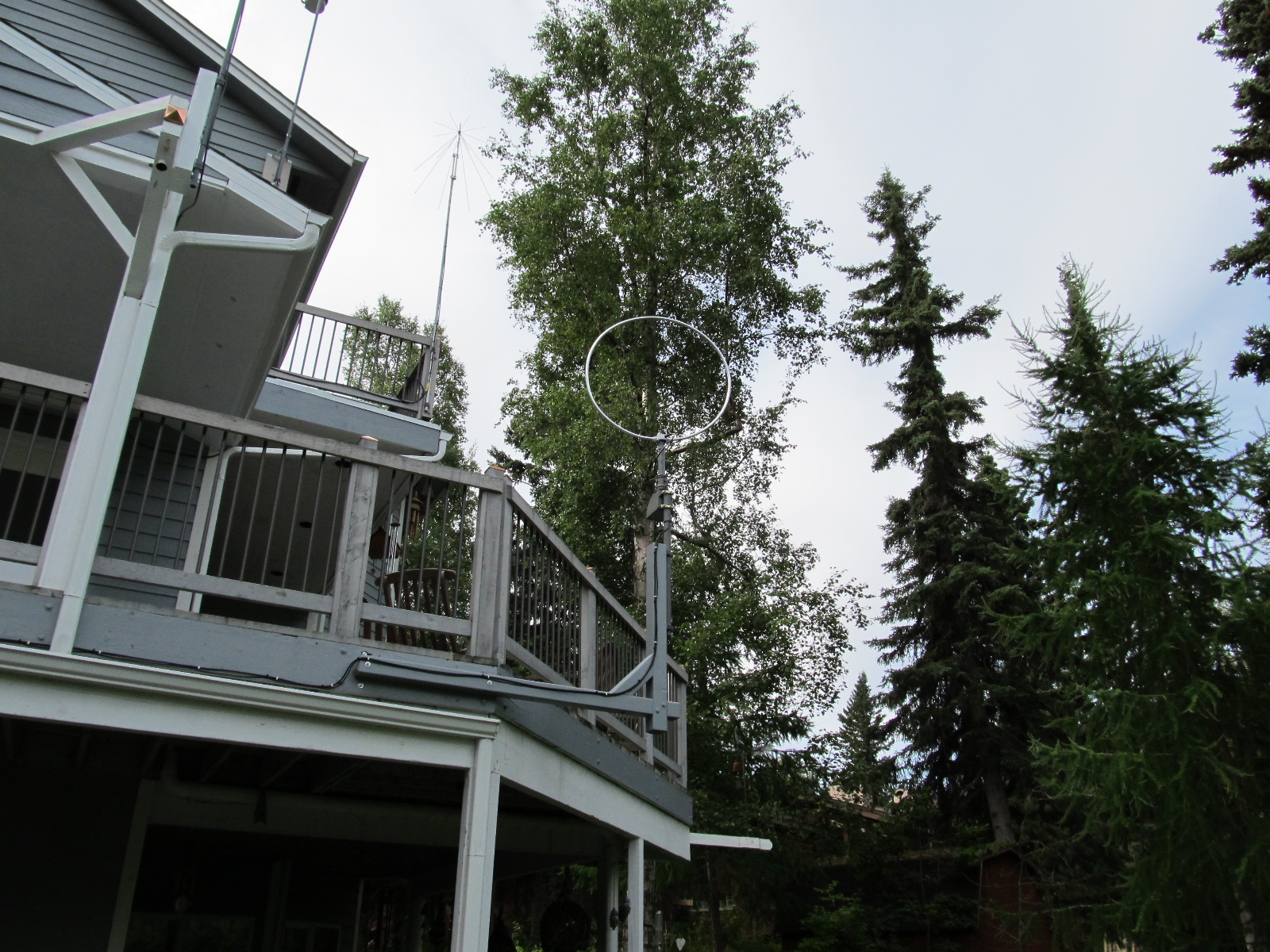


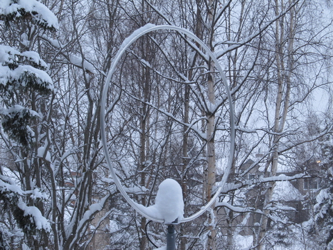

Two pictures above taken mid-day 8 January 2012
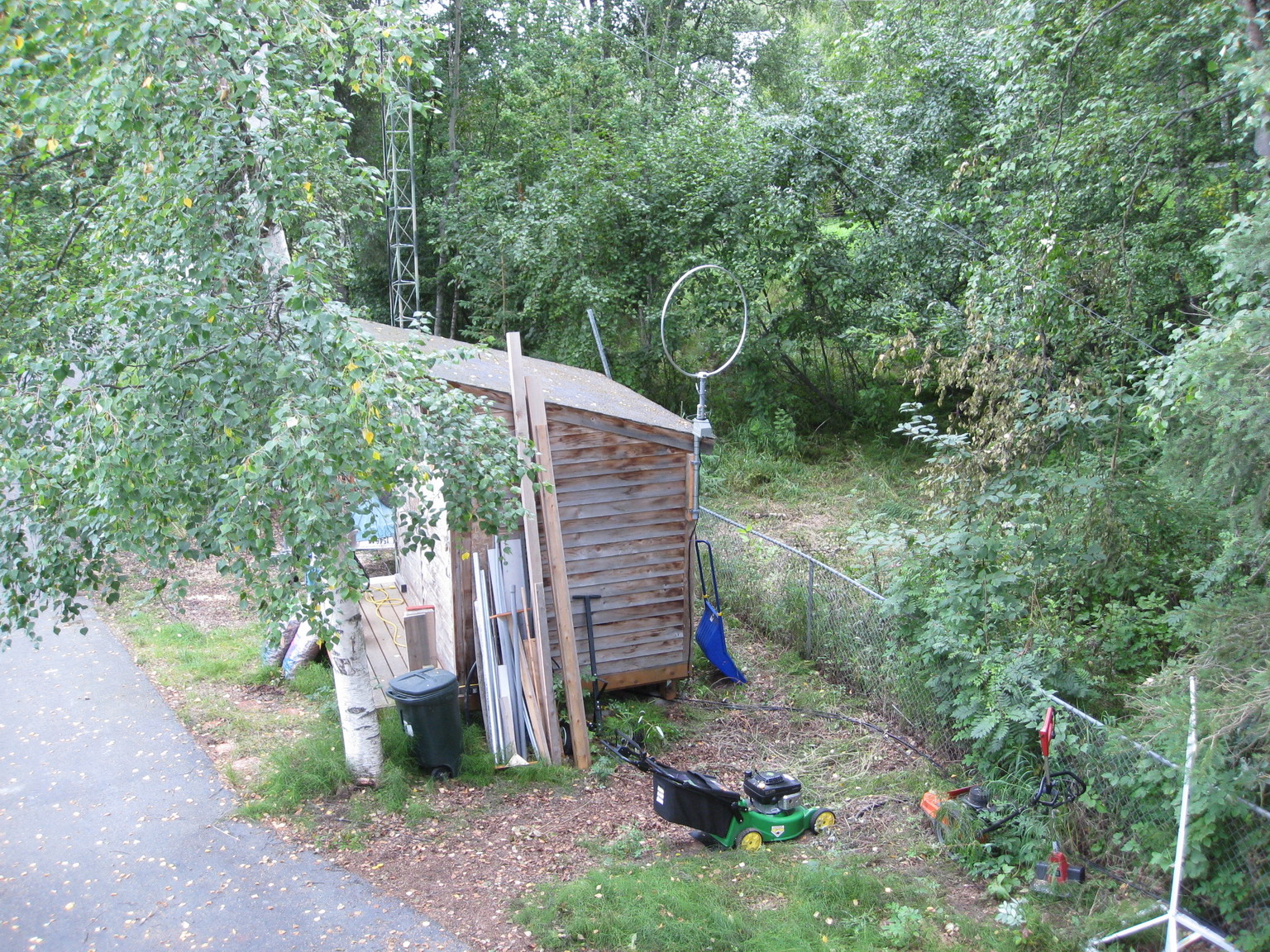
Photographs of Loop Antenna at original location
At its original location on the corner of the shed, the loop antenna was about 3 m above ground level.
Long view of loop antenna on the corner of the storage
shed.
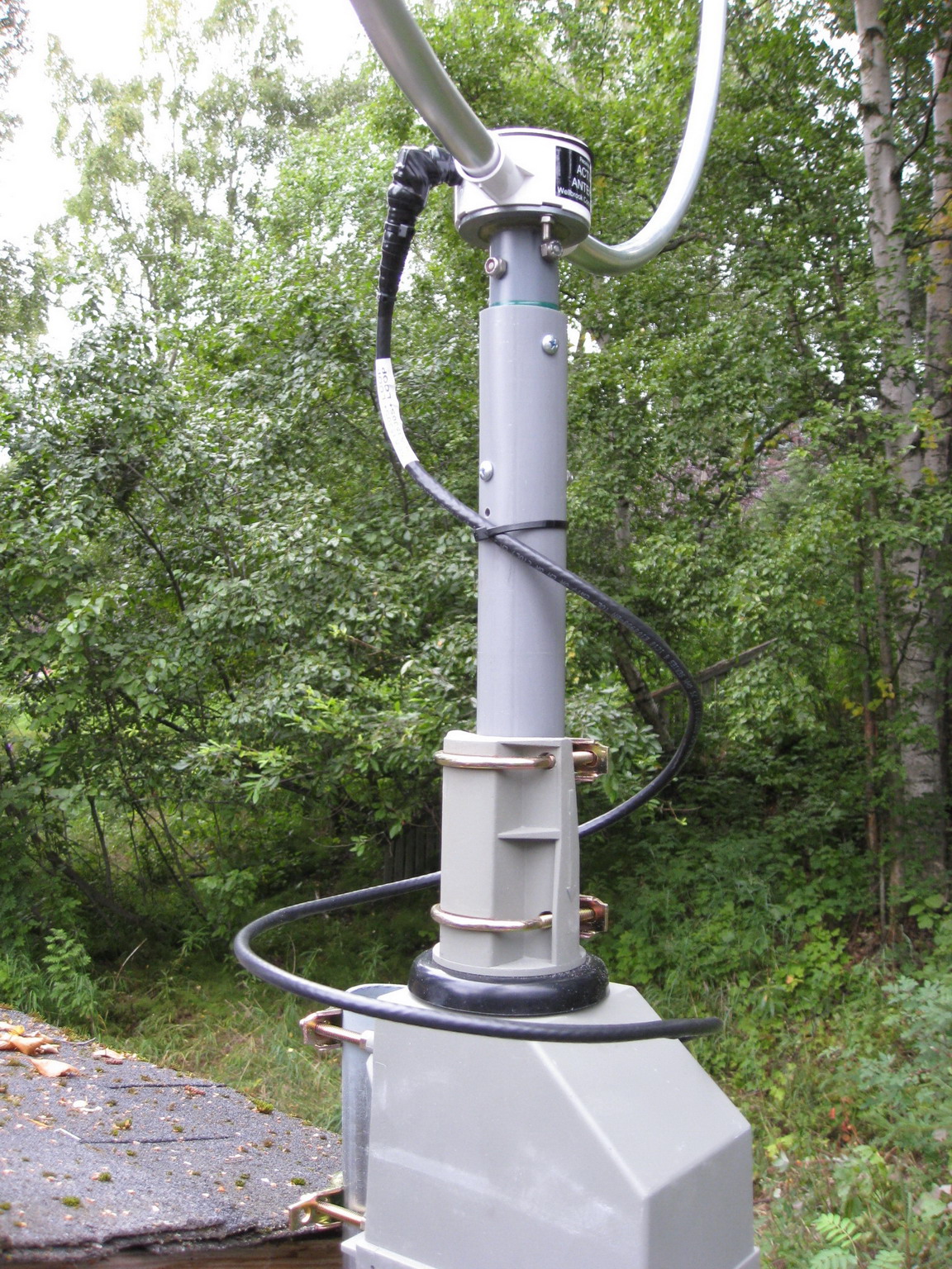
Close-up of antenna showing the mast and rotator.

This view shows the loop of coaxial cable around the
antenna mast.
The mast consists of a short section of 1 in. Schedule 40 PVC conduit
epoxied to the metric conduit fixture supplied with the antenna. The
PVC conduit also is fastened with two 10-32 machine screws to add
strength to the assembly. The 1 in. conduit is inserted in a short piece
of 1-1/4 in. PVC conduit, which is attached to the rotator. The inner
and outer PVC conduits are fastened together with two 1/4 in. bolts.
Close-up of coaxial cable connector. The antenna
interface uses a BNC
connector. A right-angle adapter was installed and the connections were
waterproofed with 3M
Temflex 2155 rubber
splicing tape overcoated
with 3M 88 vinyl
electrical tape. A small tie-wrap keeps the tape from
unraveling over time.
