Simple Aurora Monitor - SAM - Magnetometer
![]() (our
Model M2)
(our
Model M2)
Click here to go directly to live real time data.
Click here for geomagnetic reports.
The Model M2 magnetometer data acquisition system consists of the following items:
- Sensor: Speake & Co Llanfapley FGM-3 or FGM-3h
- Signal processor module: Shop built, based on the Simple Aurora Monitor (SAM) kit designed by Karsten Hansky and Dirk Langenbach
- Data logger: External logging through software
- PC software: SAM_INI (hardware parameter setup) and SAM_VIEW (software logger and output viewer)
This system is called our model M2 because it is the second magnetometer in our observatory. It is more commonly known as the Simple Aurora Monitor, or SAM. The SAM is available in kit form and we produce the kits for distribution everywhere in the world except Europe. If you are interested in purchasing a SAM kit and associated accessories, click here.
The SAM uses the Microchip PIC16F877 microcontroller and is capable of measuring the output from two magnetometer sensors (usually setup in different directions). A future version of SAM will support three sensors. Click here for a description of the magnetometer sensors in our application.
The microcontroller measures the period of the magnetometer sensor output and applies offsets and other adjustments to achieve a specified sensitivity and resolution. An output threshold may be set through software and dry relay contacts are provided for alarm activation. The signal processor functions include a real-time clock and digital-analog conversion of the microcontroller's digital output. In addition to a digital output channel that can be uploaded to an FTP server, the signal processor has two analog output channels for direct display on an analog panel meter or other indicator and includes signal balance and level adjustment.
The SAM_INI software allows offsets and adjustments to be preset, and the SAM_VIEW software provides a chart of the SAM outputs; for example (click image for real time data):

Click here to go directly to live real time data.
See below for photographs of the model M2 signal processor. It was placed in limited operational service May 27, 2009. Full operational service will be achieved when we complete scale calibration and determine an initial K-index for the station (the latter will require about 1 year).
M2 bare printed circuit board (component side) prior to installation of the components

M2 PCB after installation of components

Assembled signal processor with display, keyboard and EIA-232 interface connector.
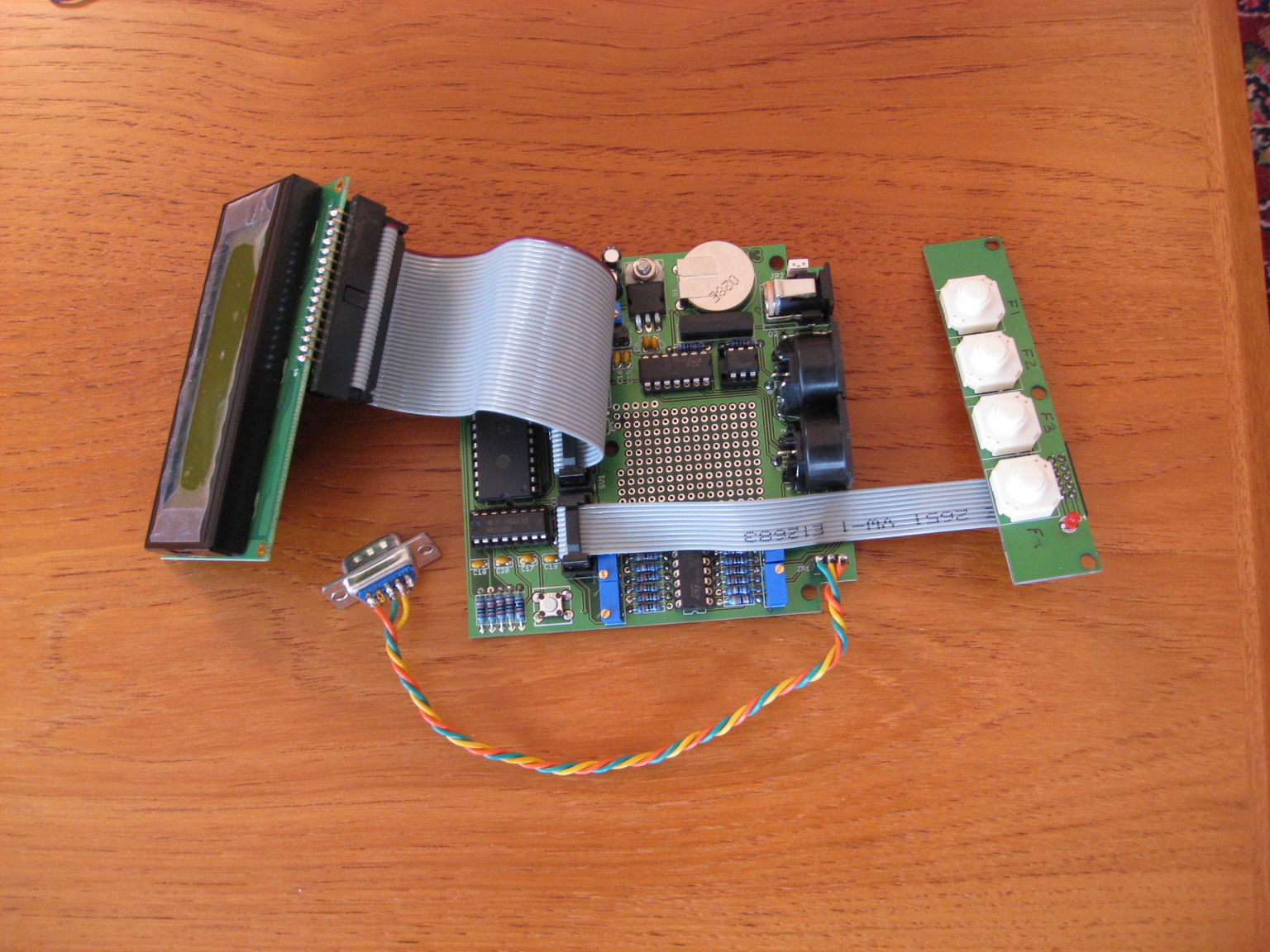
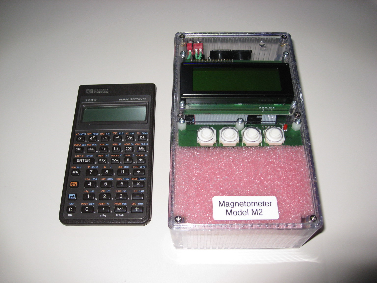
Signal processor (right) installed in a plastic enclosure with a
12 v, 0.8 ah battery,
battery fuse and polarity protection diodes.
The HP32S II calculator is for size
comparison.
This picture shows the operational signal processor
in our shop. The upper-right
cable uses a 3.5 mm stereo plug for connecting the EIA-232 data output to a
USB-serial adapter, which is connected to the observatory PC running SAM_VIEW.
The DIN connector to its immediate left is the sensor cable. To the left
of the DIN
connector are the power switches and 12 vdc power input connector. The
battery
is removed when the processor is used in our observatory.
